A hundred years ago most Hams had transitioned from Spark transmitters to the new Vacuum Tubes which, through Feedback, were able to generate just a single frequency output thus allowing more than one guy at a time to transmit without having to decipher the slightly different tonal quality of a spark to determine who it was transmitting. (The ‘T’ part of the RST signal reporting system.) Tubes allowed amplification of weak signals, and with the recently invented superheterodyne receiver system, up to and over 100 dB of receiver total gain by changing (heterodyning) the frequency of the signal several times.
Transistors (William Shockley at Bell Labs in 1947) allowed the same kind of amplification advantage without all the heat and high voltages that make tubes work. They didn’t take over right away, portable AM radio receivers in the 1950s, and some functions like the Noise Blanker in the Galaxy V five band transceiver in 1964, but by the early 1970s the Kenwood 520 five band HF transceiver had 73 of them, everything but the 12BY7 driver and two S-2001 final tubes (similar to the thirty five Watt 6146 tube).
Transistors are little, and it’s really hard to make 2 batches of them come out with same specs so the gain of a specific type can vary a lot. Example: hFE gain of a 2N2222 runs from 100 to 300. If the batch comes out really bad they call ’em 2N2221s with a gain of 40 to 120.
Differential amplifiers consist of 2 transistors (facing each other) and are really useful, a favourite circuit used in power supplies comparing half the 12V output to a 6V Zener regulating diode. It’s best when the 2 transistors have similar gains so (now) the differential is part of an Integrated Circuit IC where ALL the transistors come out with the Same Range of Gain (and the differential is thus balanced).
Transistors are still little when they handle lots of Amps, but they put them in different cases to get rid of all the heat. The 2N2222 can only handle milliwatts, or up to Half A Watt if you’re bold. The same chip in a larger (TO-5) case is called a 2N2219 and runs a maximum of 0.8 Watts. The Astron favourite 2N3771 comes in a diamond shape TO-3 case that (when well attached to a big piece of aluminum) can handle well over a hundred Watts. Calculate how an Astron 35 running at max with 21 Volts input and 14 out, divides the heat among only 4 transistors. Seven Volts across the transistors (21 minus 14) times the 35 Amps equals, uh, two hundred plus, exactly 245 Watts. Divided among the 4 transistors it’s 61 Watts or so, well within the 150 Watt rating each. Note: The Astron 35 says it’ll do 15 or 20 Amps continuous. No, it won’t. It doesn’t have a fan. Prop up a little five inch computer fan in back of it and you can do that, like, for repeater use.
We won’t meet again until 2nd Thursday in November, the 13th, so there’s plenty of time to go home and look in the back of our power supplies to see if it’s 2N3771s like on an Astron, or something else. The switcher power supplies use an even more expensive type, but you have to open the case to see what kind they are. (They run at like, 40 kc or more into a ferrite transformer, not just responding to 120 cycle ripple.)
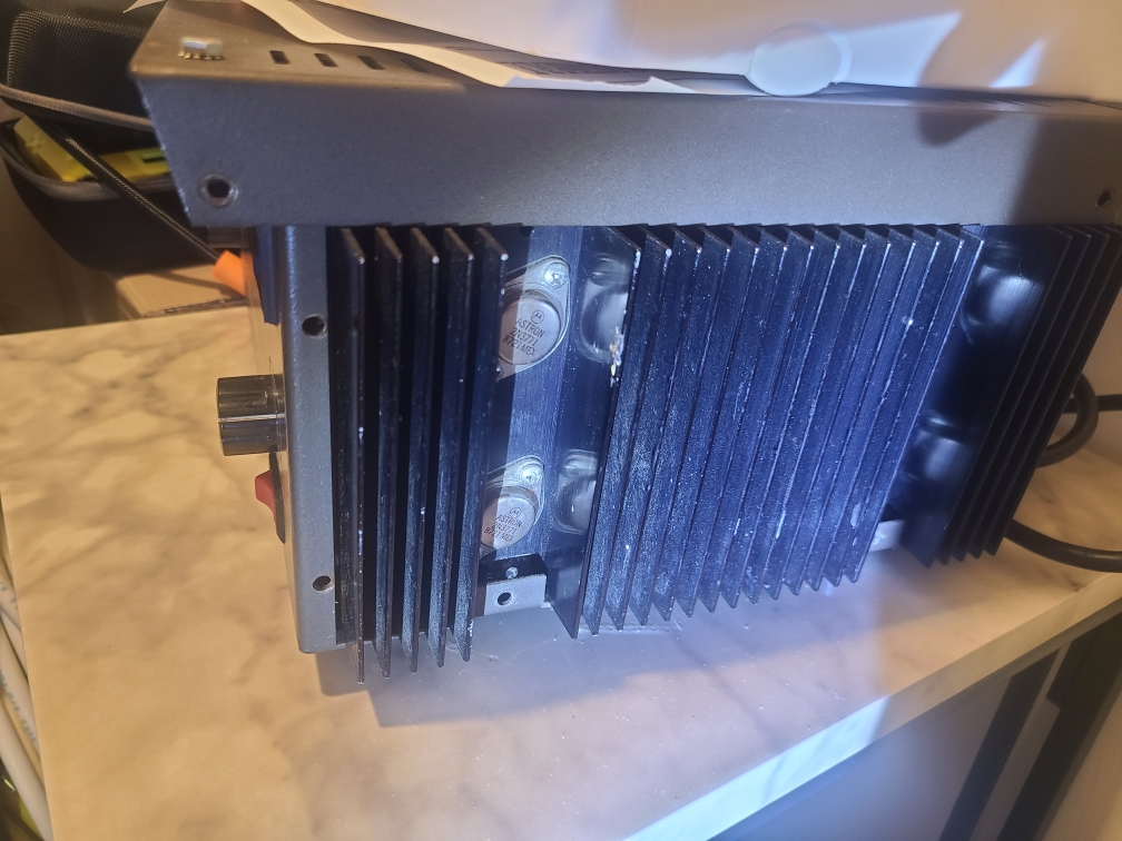
DETAIL: The pic shows right side of an Astron 50. It’s covered, both sides and back, with heat sinks. What’s the Date Code on the 3771 (YrWk). So how old is that 50?

Leave a comment